
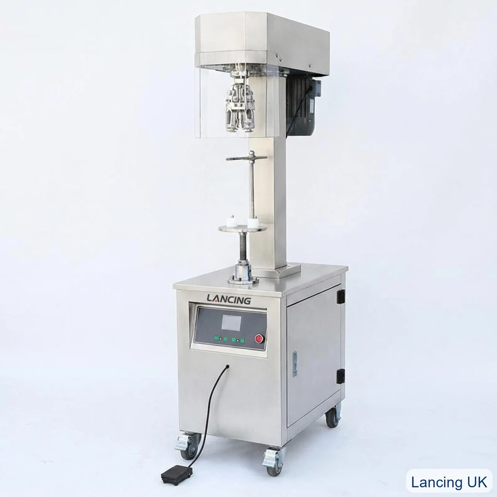
Semi-auto ROPP capper
For lower volumes, sampling and controlled operator-fed production.
View semi-auto modelChoose the right roll-on pilfer-proof capping machine for your bottle, aluminium closure, line speed and quality target. Lancing supports machine selection, tooling, samples, installation and line integration.
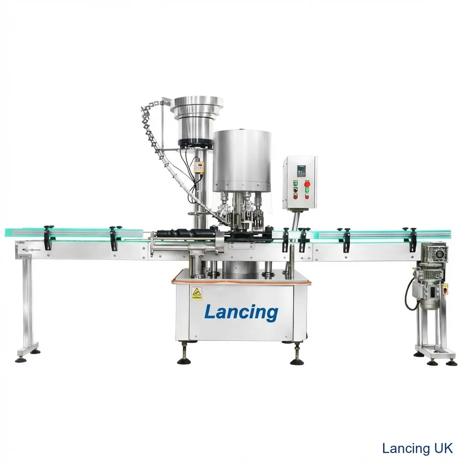
Selection guide
ROPP capping is not only about speed. Correct head pressure, cap support, roller setting, bottle rigidity and closure quality determine whether the cap seals, opens and presents correctly.
Best where operators can place caps and bottles, where volumes are controlled, or where you need flexible trials before committing to automation.
Best where a conveyor-fed line needs repeatable closing, cap sorting and reduced manual labour while keeping a compact footprint.
Best for high-throughput lines where bottle handling, cap transfer and capping head sequence must be synchronised at speed.
Compare the range
Use this as a first shortlist, then confirm the project with real samples.
| Model / type | Ideal use | Output guidance | Format notes | Typical options |
|---|---|---|---|---|
| Semi Automatic ROPP Capping Machine | Pilot lines, small production, product development, contract packing trials | 25–30 bottles/min depending on operator workflow | 20–50mm cap diameter; 60–350mm bottle height | Selected ROPP head size, guarding, bottle support, foot pedal operation |
| Automatic ROPP Pilfer Proof Capping Machine | Inline beverage, wine, oil, spirits and general liquid packaging lines | LU-XG440C 2,000 pcs/h; LU-XG440C4 4,500 pcs/h; LU-XG440C6 6,000 pcs/h; LU-XG440C8 8,000 pcs/h | Configured to cap, bottle, conveyor and required units per hour | Stainless conveyor, cap sorter, star wheel, line controls, integration |
| LU-XG440C8 8-Head ROPP Capping Machine | Higher-speed glass bottle lines needing repeatable rotary ROPP application | 7,500 pcs/hour reference specification | Φ30–90mm bottle diameter; Φ22–38mm mouth; 100–330mm bottle height | Vibratory bowl feeder, turret tooling, bottle handling, change parts |
Configuration
The capping head must be chosen for the exact cap and bottle neck. The set-up normally includes a pressure block, thread rollers, lower pilfer band rollers and bottle support. Poor matching can cause loose caps, excessive opening torque, damaged bridge perforations, misshaped threads or bottle collapse.
For lower volumes, sampling and controlled operator-fed production.
View semi-auto model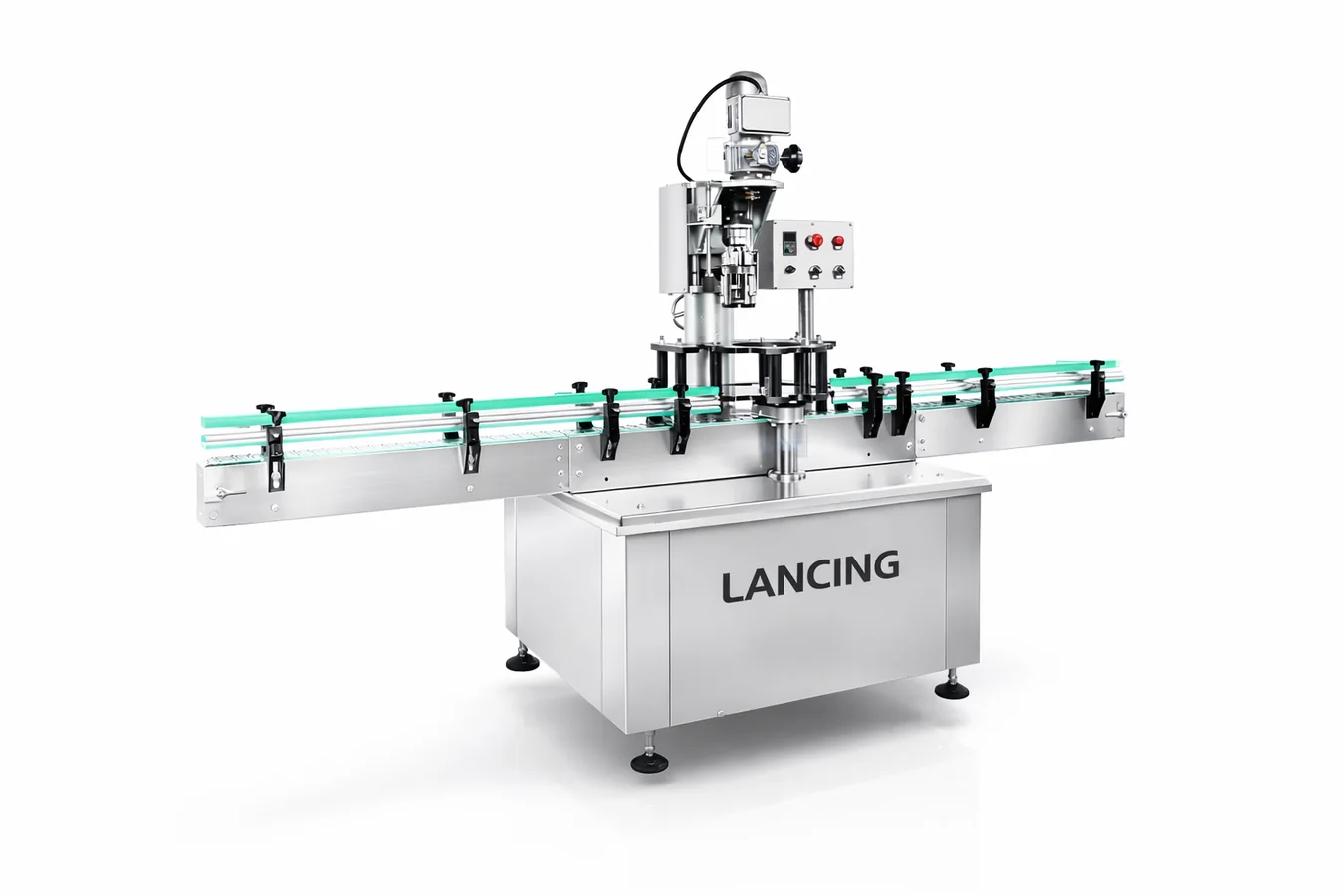
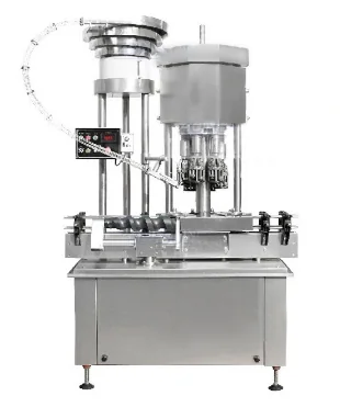
For higher output applications and multi-head turret operation.
View 8-head modelMachine FAQ
A semi-automatic ROPP capper is usually the safest starting point when volumes are low, formats are still changing, or the production team needs hands-on control.
Move to automatic ROPP capping when throughput, labour cost, cap consistency or integration with filling and labelling makes manual loading the bottleneck.
The capping head and rollers are selected around the cap diameter, cap height, neck finish and closure specification. Some machines can be changed over, but tooling compatibility must be confirmed.
Send bottle height, cap diameter, line speed and product type. Lancing will advise the right machine format.
Evidence-led selection
The correct ROPP machine format is the one that can form the agreed closure quality repeatedly while fitting the real production pattern. Batch size, cap presentation, bottle stability, changeover frequency and inspection requirements can be more important than the highest published output.
| Decision | Semi-automatic | Inline automatic | Rotary multi-head |
|---|---|---|---|
| Production pattern | Trials, short campaigns, flexible operator-led batches. | Repeated conveyor-fed production with automated cap delivery. | Stable high-output production with synchronised bottle and cap handling. |
| Cap presentation | Normally placed by the operator. | Usually sorted and delivered to a placement point or capping head. | Continuous cap feed matched to turret demand and transfer geometry. |
| Bottle handling | Adjustable platform or support, with operator control of presentation. | Guides, spacing and support arranged around the existing conveyor. | Starwheels, turret timing and change parts matched to the bottle. |
| Changeover | Often practical where formats change frequently and output is moderate. | Requires documented guide, height, feeder and head settings. | Requires a defined change-parts strategy and repeatable set-up record. |
| Acceptance evidence | Operator method, first-off samples, torque/leak checks and timed batch. | Cap-feed reliability, line stops, restart behaviour, reject rate and quality checks. | Head-by-head samples, turret performance, feeder supply and agreed timed run. |
Machine trial plan
A useful trial does more than show that a cap can be applied. It creates a repeatable record that production and maintenance teams can use after installation.
List the capping head, pressure block, thread rollers, pilfer-band rollers, bottle supports, guides, starwheels and cap-feed parts required for each approved format. Mark shared parts and format-specific parts clearly.
Use representative production bottles and closures, not only hand-selected samples. Identify the packaging lot and retain approved capped samples so later set-ups can be compared with the original trial.
Agree visual checks, opening-torque method, leak method, tamper-band condition, cap finish and permissible reject conditions. Where the product affects the liner or sealing surface, include filled-pack checks.
This site owns the ROPP closure-forming decision. Projects centred on non-ROPP cap types should use the wider capping machine selection route. Dedicated cap orientation and bulk feeding is covered by Cap Feeders UK, while complete multi-machine layouts can be reviewed through Packaging Lines UK.
Lancing can review the bottle, ROPP closure, line layout and acceptance requirements before quotation.
Selection boundaries
Semi-automatic, inline and rotary machines all form the same essential ROPP interfaces, but they distribute bottle handling, cap presentation, settings, inspection and fault recovery differently. The correct format is the one that matches the production pattern and can be verified with the intended pack.
| Selection question | Semi-automatic route | Inline automatic route | Rotary multi-head route |
|---|---|---|---|
| Who places the cap? | The operator normally places and visually checks each closure. | A feeder or transfer mechanism presents caps to conveyor-fed bottles. | A continuous feeder and transfer system must match turret demand and timing. |
| How is the bottle located? | By the operator and adjustable bottle support or platform. | By guides, spacing devices and supports around the conveyor transfer. | By format-specific starwheels, guides, turret timing and bottle support. |
| How is quality traced? | By batch, operator method, first-off approval and periodic samples. | By time, machine state, head where applicable, packaging lot and line event. | By head number, packaging lot, run state, feeder condition and retained sequence. |
| What drives changeover effort? | Head height, bottle support, cap size, roller settings and operator instructions. | Those items plus guides, spacing, cap-feed parts, sensor positions and line controls. | Those items plus starwheels, turret parts, synchronisation and head-by-head verification. |
| What should trigger an upgrade? | Manual handling limits output or cap placement becomes the main source of variation. | Continuous demand, cap-feed rate or line synchronisation exceeds the practical inline arrangement. | The pack and production pattern are stable enough to justify format parts and multi-head control. |
ROPP equipment forms an aluminium shell around the bottle finish. If the closure is already threaded and only needs tightening, compare the wider capping machinery range or the dedicated screw capper route rather than forcing the application onto a ROPP page.
Cap storage, orientation, transfer, low-level response, refill method and finish protection can decide whether an automatic line is stable. Where a dedicated feeding study is required, use Cap Feeders UK and include the agreed interface in the capper acceptance test.
Upstream filling, accumulation, capping, inspection, labelling and downstream blocking must be treated as one flow problem. A full layout is better handled through Packaging Lines UK, while this site remains the technical owner of the ROPP forming station.
Machine release pack
A quotation identifies scope; a release pack makes the approved result repeatable. It should be specific to each bottle-and-closure format and should remain usable by production, quality and maintenance teams after installation.
Use the blank acceptance checklist to align the semi-automatic, inline or rotary trial before deciding which route fits production.
Selection evidence
A machine comparison is strongest when it records the run pattern, format range, cap-supply method and accepted-output condition rather than relying on nominal speed alone.
| Selection question | Semi-automatic evidence | Inline / rotary evidence |
|---|---|---|
| How are caps presented? | Operator places and visually checks each cap before the cycle. | Cap storage, orientation, chute buffer, transfer and low-cap response are part of the production scope. |
| How stable is the format? | Useful where batches are controlled, formats change frequently or specialist bottles need manual attention. | Best justified when bottle and closure supply are stable enough for repeatable feeding, transfer and change parts. |
| How is output defined? | Accepted bottles per observed period, including operator handling and inspection. | Accepted finished bottles under the stated feeder, line-flow, stop and reject conditions. |
| What must be trialled? | Bottle support, head setting, cap placement, first-off approval and operator method. | All semi-auto pack checks plus cap feed, bottle transfer, every head/station, fault recovery and connected-line behaviour. |
| What changes at installation? | Workstation, utilities, safe access and material flow. | Conveyors, signals, cap supply, accumulation, guarding interfaces, inspection and SAT. |
Existing model figures on this site identify the source machine range. Final acceptance should state the actual bottle, closure, cap feed, format, operator or line arrangement, run duration, stops, rejects and finished-pack tests.
Confirm the pressure pad, roller profile, bottle support, guides, starwheels and cap-feed parts from approved samples. Use the sample-trial route before format parts are frozen.
Single-head and multi-head systems need different sampling plans. Use the quality guide and FAT checklist to define traceability.
Send the same packaging, output, line and quality information for each configuration so the proposals are genuinely comparable.
Machine comparison questions
Use the same pack and acceptance definition so architecture, output and project scope can be compared honestly.
Issue the same pack, format list, output definition, line boundary and acceptance criteria to both suppliers. Compare included cap feeding, change parts, controls, guarding, trials, installation and support as well as the machine architecture and price.
A single-head automatic arrangement can be preferable when the required accepted output, format range, space, changeover needs and project complexity do not justify a rotary multi-head system. The decision should use a connected-line trial and total scope, not head count alone.
Include the exact bottle and cap, cap-feed conditions, run duration, line speed, stops, restarts, rejects, quality sampling, changeover state and the definition of an accepted bottle. Without these conditions, two output figures may not describe the same task.
Future bottles and closures can change the required adjustment range, guides, supports, starwheels, feeder tracks, capping heads and set-up method. Include credible future formats before architecture selection, then identify which remain subject to samples and engineering review.
Comparable machine evidence
Compare each architecture using the same bottle and closure, accepted-pack definition, run duration and quality checks. Include operator work for semi-automatic equipment and cap feeding, bottle transfer, stop recovery and every capping head for automatic equipment.
| Architecture | Output condition to record | Decision evidence |
|---|---|---|
| Semi-automatic | Named operator method, cap placement, loading/unloading and inspection workload. | Accepted bottles, pauses, handling consistency and first-off approval. |
| Inline automatic | Cap-feed condition, bottle spacing, connected conveyors, stop/restart and reject route. | Timed accepted output, fault recovery and stable transfer through the line. |
| Rotary multi-head | All heads/stations identified and sampled under the agreed connected-line condition. | Head-by-head quality evidence, rejects, stops and accepted production rate. |
Beyond the basic machine shortlist
A ROPP capper is one part of a controlled packaging process. The surrounding components and evidence can determine accepted output as much as the nominal machine architecture.
Where a pourer or anti-refill insert is involved, review the complete bottle–insert–shell assembly rather than selecting from cap diameter alone.
Define which visible cap faults require 100% automatic checking and which functional properties remain subject to sampled tests.
Record machine, tooling and approved-pack references from commissioning so future service work starts from traceable evidence.