
Cap feeding
Confirm bulk storage, orientation method, chute or transfer geometry, low-cap sensing and the way the capper stops when supply is interrupted. Dedicated feeder design is covered by Cap Feeders UK.
Conveyor-fed automatic ROPP capping for beverage bottle caps, wine bottle caps, olive oil bottle caps, spirits and compatible aluminium pilfer-proof closures.
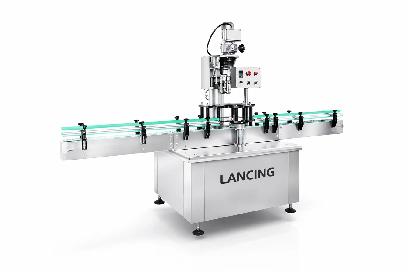
Machine overview
The automatic ROPP pilfer proof capping machine is designed for lines where bottle flow, closure feed and cap application need to be synchronised. It is suited to screw-style pilfer-proof aluminium caps that are formed onto the bottle neck by the capping head.
Typical applications include beverages, wine, spirits, olive oil and premium liquids where tamper evidence, resealability and cap presentation are important.
Reference output range
Actual output depends on cap, bottle, machine configuration, product, upstream filling speed and downstream constraints.
| Model | Reference capping speed | Recommended use |
|---|---|---|
| LU-XG440C | 2,000 pcs/h | Entry automatic line or moderate output requirement |
| LU-XG440C4 | 4,500 pcs/h | Multi-head automatic line with higher production demand |
| LU-XG440C6 | 6,000 pcs/h | Higher-speed packaging operations |
| LU-XG440C8 | 8,000 pcs/h reference range | Rotary/high-output ROPP capping requirement |
Gallery
Automatic capping head with conveyor flow.
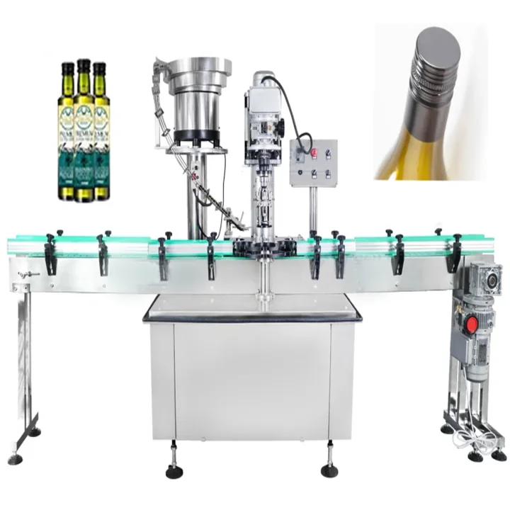
Configured for closure and bottle format.
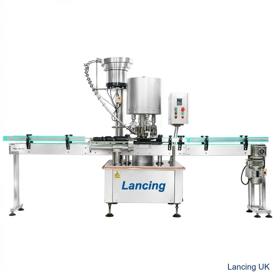
Designed to work with filling and labelling systems.
Integration
Lancing can support ROPP capping as a stand-alone upgrade or as part of a wider bottling line. Integration considerations include conveyor pitch, bottle stability, cap feed position, reject/inspection requirements, line guarding, operator access and changeover workflow.
Automatic FAQ
It is used for automatic application of roll-on pilfer-proof aluminium caps, including compatible beverage, wine, spirits and olive oil bottle caps.
Reference speeds in the supplied range include 2,000 pcs/h, 4,500 pcs/h, 6,000 pcs/h and up to 8,000 pcs/h depending on model and project configuration.
Yes. It can be specified around conveyor flow, filling machines, labellers, cap feeding, coding and downstream packaging.
Tell Lancing your target output, bottle shape, cap size and existing conveyor layout.
Line acceptance
Automatic ROPP performance depends on more than the forming head. Bottle spacing, cap orientation, placement, conveyor transfer, stop/start logic and downstream flow must work together before a headline output can be accepted.
| Line zone | What to confirm | Evidence for the acceptance record |
|---|---|---|
| Infeed | Bottles arrive upright, correctly spaced and stable at the capping transfer. | Line speed, guide settings, accumulation condition and any bottle damage. |
| Cap supply | The production closure is separated, oriented and delivered without starvation or damaging the finish. | Cap lot, feeder settings, refill method, jams, misfeeds and recovery method. |
| Cap placement | Caps arrive square and at the correct height before the forming cycle. | Placement photographs, rejected-cap cause and sensor response. |
| ROPP forming | Liner compression, thread definition, band tuck and cap appearance meet the agreed standard. | Head-traceable samples, opening torque, leak method and visual results. |
| Outfeed and controls | Capped bottles leave without back pressure, and the capper responds correctly to upstream/downstream stops. | Interlock tests, restart behaviour, reject handling and fault log. |
Integration and changeover
The capping machine cannot recover consistently from cap starvation, unstable bottles or poorly defined change parts. These interfaces should be included in the quotation and trial plan rather than left until installation.
Confirm bulk storage, orientation method, chute or transfer geometry, low-cap sensing and the way the capper stops when supply is interrupted. Dedicated feeder design is covered by Cap Feeders UK.
Define start, stop, emergency stop, upstream/downstream permissives, bottle-no-cap and cap-no-bottle logic, fault indication and the required interface with the existing line controls.
List guides, starwheels, cap-feed parts, capping-head settings and bottle supports for every approved format. Label parts and record the set-up that produced the accepted samples.
Record routine inspection points for the pressure block, thread rollers, pilfer-band rollers, head bearings, bottle-handling parts and cap-delivery surfaces. The maintenance schedule should reference the actual machine manual and the closure quality checks used by production.
For the higher-output rotary route, compare the LU-XG440C8 page. For detailed fault diagnosis, use the troubleshooting guide.
Project FAQ
Not unless the trial protocol says so. The acceptance test should define whether hopper refilling, cap starvation, line stops, rejects and inspections are included in the measured result.
Yes where the machine has multiple heads. Head traceability helps identify one incorrect setting or worn component that would be hidden in an overall average.
Often it can be integrated, but conveyor height, speed range, bottle stability, available length, controls and upstream/downstream accumulation must be reviewed first.
Include every approved bottle and cap format, with required guides, starwheels, supports, head or roller parts, cap-feed parts, settings and storage or identification needs.
Review rotary equipment when the required accepted output, bottle consistency and production pattern justify synchronised multi-head operation and the associated change-parts and cap-feed system.
Send the line layout, bottle and cap samples, speed target, control interfaces and quality method.
Controls and recovery states
Stable production depends on controlled recovery as well as steady running. The required sensors, interlocks and messages are project-specific, so the quotation and acceptance plan should state which abnormal conditions must be detected and how the line should stop, hold or restart.
| Line condition to define | Project decision | Acceptance evidence |
|---|---|---|
| Irregular bottle infeed | How spacing, unstable bottles, fallen bottles and upstream accumulation are controlled before cap placement. | Video and fault log showing the agreed response without bottle or closure damage. |
| Low or interrupted cap supply | Whether low-level warning, controlled stop, buffer capacity or operator refill instruction is required. | Time-stamped test of warning, starvation response, refill and recovery. |
| Missing or mis-presented cap | Whether detection, rejection or line stop is required and where the decision is made. | Deliberate challenge samples and confirmed reject or stop behaviour where specified. |
| Feeder or transfer jam | Safe access, fault indication, restart sequence and protection of decorated aluminium closures. | Recorded jam simulation, clearance method and first-off quality after restart. |
| Downstream blocked | How the capper reacts to stopped labelling, inspection, accumulation or packing equipment. | Blocked-line test showing controlled deceleration, bottle retention and restart. |
| Emergency or planned stop | Disposition of bottles and caps already inside the process and the checks required before release. | Stop/restart sample sequence with cap placement, forming and quality results. |
Interface schedule
A capper can form an acceptable closure at low speed while still failing as a production system if bottle flow or cap delivery is unstable. The line acceptance record should identify the owner, signal and recovery method for every interface.
Record bulk loading, orientation, transfer path, cap-contact surfaces, refill frequency and low-cap response. For a dedicated study of cap handling, use the specialist cap feeder route and carry the agreed handover point into the capper FAT.
Define conveyor height, bottle pitch, guide position, transfer gaps, accumulation pressure and the conditions at which the capper may start or stop. Lightweight or unstable containers may need additional support beyond simple side guides.
List start permissives, healthy signals, blocked/starved states, faults, emergency-stop boundary and restart responsibility. Complete filling-to-packing projects can be coordinated through Packaging Lines UK.
Use the acceptance checklist to define bottle flow, cap supply, abnormal conditions and finished-pack checks before the project trial.
Automatic system boundary
The capping head cannot sustain accepted output if caps arrive damaged, bottles queue unpredictably or the line restarts without controlling uncertain packs.
| Interface | Information to define | Acceptance evidence |
|---|---|---|
| Cap supply | Bulk loading, orientation, chute buffer, cap-low and jam response, decorated-cap handling. | Normal replenishment, low-cap, stop/restart and scuffing checks with production closures. |
| Bottle infeed | Conveyor height, guide range, spacing, bottle-present detection and upstream release. | Stable transfer without skew, double feed, bottle damage or cap-placement disturbance. |
| Capping station | Head count, bottle support, tooling, format parts and head/station identification. | Traceable samples from every relevant head using the agreed visual, opening and seal methods. |
| Outfeed and inspection | Cap presence, reject route, coding/labelling handover, blocked-line response and accumulation. | No uncertain bottle released after a fault; documented reject classification and recovery. |
| Controls | Ready, run, stop, fault and emergency-stop boundaries with adjacent equipment. | Witnessed functional sequence and site handover list. |
Review closure geometry, liner/insert, decoration and required rate through the complete orientation and transfer path.
Confirm floor plan, access, conveyors, project utilities, signal ownership and SAT packaging before delivery.
Define accepted output, head sampling, quality methods, stops, rejects and fault recovery in the witness plan.
Send the cap and bottle drawings, samples, layout, target accepted output, cap-supply method and connected-machine details.
Automatic line-control questions
The capper, cap feeder, conveyors and neighbouring machines need one written response for missing caps, invalid bottle positions, stops and rejects.
The agreed control strategy should prevent an uncapped bottle from being released as accepted production. Depending on the system, it may inhibit bottle feed, stop the relevant equipment, identify or reject the bottle and generate an operator alarm. The exact action belongs in the line functional specification.
Sensors and bottle-handling logic should prevent cap release or head operation when the bottle position is invalid and should stop or contain a blockage before equipment or packaging is damaged. Test the defined conditions during FAT and connected-line commissioning.
There is no universal owner. The line-control design should define who initiates each stop, which equipment completes or aborts its current cycle, how accumulation is used and how restart is authorised. Document the signal list and stop hierarchy before controls are finalised.
The line should identify, segregate and account for bottles that lack a cap, have an unverified closure or were produced during a fault window. The reject method and downstream route must suit the line risk and prevent unverified bottles from rejoining accepted production.
Automatic line functional scope
Agree who owns run permission, ready, starved, blocked, cap-low, fault, emergency-stop boundary, reject confirmation and restart. Each state needs a source, destination, normal condition, required response and reset rule so an uncertain bottle cannot silently rejoin accepted production.
Define bottle release, cap availability, spacing, capping enable, downstream acceptance and accumulation limits.
Test no cap, no bottle, double bottle, cap jam, blocked outfeed, guard opening, power interruption and inspection/reject faults.
State which bottles are cleared, rejected or rechecked, who authorises reset and how the line returns to stable production.
Automatic-line quality control
It may be appropriate where the quality plan requires every bottle to be checked for a defined visible or measurable cap condition. Selection should start with representative faults and the required containment response, not with a camera specification alone.
The connected system must maintain bottle identity from inspection to rejection, confirm the rejected pack reached the controlled destination and stop or hold the line when reject integrity is uncertain. Sampled torque, opening, leak or insert tests remain separate unless the automatic method directly measures them.