
Bulk supply and orientation
Control how caps enter the device, prevent overfilling and keep foreign material out. The orientation method should reject or recirculate incorrectly presented caps without creating damage or unstable surges.
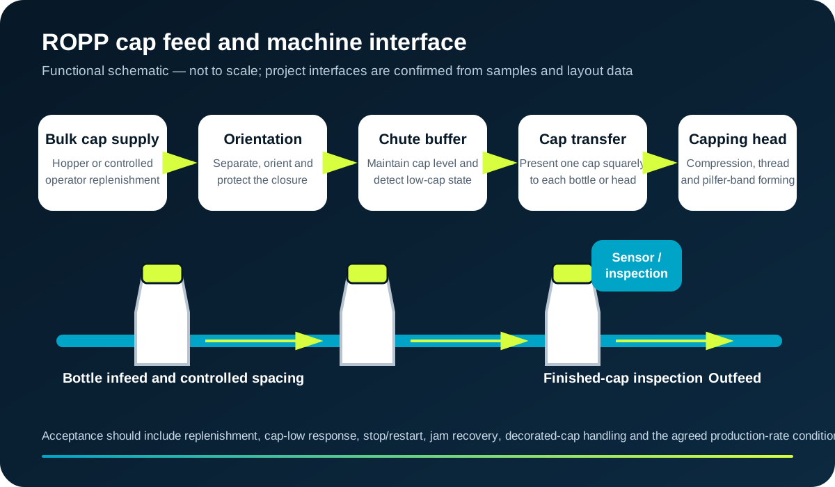
Reliable automatic ROPP capping begins before the capping head. Caps must be stored, separated, oriented, buffered and transferred without damaging the aluminium shell, liner, pilfer band or decoration.
Direct answer
The feeder has to deliver one cap in the correct orientation at the point and rate required by the machine. The practical system can include bulk storage, controlled replenishment, an elevator or operator loading point, an orientation mechanism, a lined track or chute, a buffer, cap-level sensing and the final transfer to the bottle or capping head.
Closure geometry is only one input. Aluminium shells can be marked by excessive contact; liners or inserts can change mass distribution; pilfer-band features can catch; and decorated finishes may set a tighter scuffing limit. Representative production caps should therefore be trialled through the complete feed route.
Interface chain
Control how caps enter the device, prevent overfilling and keep foreign material out. The orientation method should reject or recirculate incorrectly presented caps without creating damage or unstable surges.
The chute should maintain orientation, protect the shell and provide enough controlled reserve for normal replenishment. Cap-low, cap-present and jam sensing need accessible recovery routes.
The final transfer must present a single cap squarely and in phase with the bottle or head. Define bottle-present logic, feeder-ready signals and what happens to an uncapped or uncertain bottle after a stop.
Failure modes
Trace the sample back through the cap path before changing the forming rollers.
| Observed problem | Feed evidence to check | Acceptance test |
|---|---|---|
| Caps bridge or stop flowing | Hopper level, cap geometry, contact surfaces, static, contamination and transition angles. | Run normal replenishment and controlled low-level conditions using production caps. |
| Cap arrives inverted or skewed | Orientation rejection, track width, chute transitions, transfer timing and bottle location. | Record misorientation and recovery during the defined timed run. |
| Decorated shell is scuffed | Incoming cap condition, rubbing points, recirculation route, impact and accumulated cap pressure. | Compare uncapped incoming caps with caps sampled at each transfer stage. |
| Double cap or cap overlap | Singulation, escapement timing, cap-present sensing and restart sequence. | Challenge stop/restart and blocked-chute conditions safely under the agreed test plan. |
| Cap shortage stops the machine | Buffer capacity, cap-low signal, refill method and feeder/capper handshake. | Demonstrate warning, controlled stop, refill and restart without releasing uncertain bottles. |
| Liner or insert displaced | Cap handling route, drop height, vibration, recirculation and supplier packaging. | Inspect caps before and after feeding using the supplier-approved criteria. |
Controls and ownership
For a stand-alone capper, the cap-feed device may be part of the same machine supply. On a larger line, bulk storage, elevator, sorter, chute and capper can have separate owners. Define mechanical handover dimensions, electrical signals, fault messages, safe access, cleaning and change parts in one interface schedule.
Where a dedicated cap-feeding project is required, the specialist Lancing cap-feeder site covers broader bowl, elevator and orientation applications. This ROPP page remains focused on the interface that protects closure quality and sustains the capper.
Use the blank checklist to capture closure evidence, feeder functions, capper signals, recovery tests and acceptance records.
Download the ROPP cap-feeder checklist
Selection boundary
Useful for trials, small batches, unstable closure supply or frequent specialist formats where an operator can inspect and place each cap before semi-automatic forming.
Appropriate where the cap format is stable, production demand supports continuous supply and the complete feed path can be validated without unacceptable marking or damage.
A semi-automatic project can still document closure data and cap-feed constraints so later automation does not require the packaging interface to be rediscovered.
Buyer questions
Suitability depends on closure geometry, stability, liner or insert construction, decoration and the required rate. Physical trials are needed before a feeding method is confirmed.
The answer depends on capper demand, refill method, feeder response and permitted stoppage. Define the required behaviour rather than applying a universal quantity.
It should be tested under the agreed production condition, including normal replenishment, stops and restart. The run definition and accepted-bottle count must be recorded.
Projects may use feeder ready, cap low, jam/fault, run permission and controlled-stop signals, but the final schedule depends on the machine and line controls.
Inspect caps at incoming supply, after orientation, in the chute and after capping. This locates whether the mark occurred in packaging, feeding, transfer or forming.
Send the closure drawing, production caps, decoration standard, required output, refill method and line-control requirements.
Assembled closures
The answer depends on whether the insert is preassembled into the shell, fitted to the bottle before capping or supplied as a separate component. Each route changes the centre of mass, orientation features, handling surfaces, chute geometry and permissible contact points. A feeder proven with an empty aluminium shell may not control the assembled closure in the same way.
Trial production-equivalent component lots and record scuffing, separation, inversion, nesting, jams and insertion damage. The closure supplier’s handling instructions remain the governing reference.