
Visual and dimensional
Check cap height, square placement, sidewall marking, thread definition, band position, bridge condition and bottle damage against an approved sample or drawing.
A practical engineering guide to roll-on pilfer-proof caps, capping heads, roller settings, tamper bands, torque testing and machine selection.
ROPP closure anatomy
A roll-on pilfer-proof closure is normally an aluminium cap with a liner and a perforated lower band. It arrives unthreaded or only partially shaped. The capping machine applies top pressure, rolls the skirt into the bottle thread profile and forms the security band under the neck bead.
Once opened, the bridges between cap and band break. The main cap can be screwed back on, while the separated lower band remains as tamper evidence.
ROPP process sequence
This sequence is a practical overview. Actual head design and roller timing can vary.
The cap is manually placed or automatically fed. Bottle guides, star wheels or supports hold the bottle in a repeatable position.
The pressure pad compresses the liner against the bottle finish. Too little pressure risks leaks; too much can affect opening performance or damage containers.
Rollers press the aluminium cap into the bottle neck threads. Correct thread definition gives smooth opening and re-closing.
Lower rollers form the tamper-evident band under the neck bead. The band should be secure but not distorted.
Cap height, thread detail, band position, opening torque, leak performance and visual finish are checked before production sign-off.
Comparison
| Closure type | How it closes | Strengths | Considerations |
|---|---|---|---|
| ROPP | Aluminium shell is rolled onto the bottle to form thread and pilfer band | Premium finish, tamper evidence, resealable, common for spirits/wine/oils | Needs matching cap, bottle finish, roller setup and torque testing |
| Pre-threaded screw cap | Cap threads are already formed and machine applies tightening torque | Fast, simple, common for many plastic closures | Tamper evidence depends on cap design; torque control is key |
| Crown cap | Metal crown is crimped around bottle lip | Reliable for beer and carbonated drinks | Normally not resealable without secondary closure |
| Crimp cap | Closure is crimped onto neck or vial finish | Strong seal for specific applications | Typically not designed for consumer resealing like ROPP |
| T-cork | Stopper is pressed into bottle neck | Premium spirits presentation | Different sealing and insertion process; no rolled pilfer band |
Troubleshooting
Use this table to prepare better samples and speed up engineering diagnosis.
| Issue | Likely causes | Checks |
|---|---|---|
| Cap leaks | Low head pressure, poor liner contact, damaged neck finish, product on seal, closure mismatch | Inspect sealing surface, run leak test, confirm liner and cap height, adjust pressure |
| Opening torque too high | Excessive compression, friction at seal, thread over-forming, band over-tuck | Measure torque, inspect thread profile, compare dry/wet samples, check cap lacquer/liner |
| Opening torque too low | Insufficient thread formation, inadequate top pressure, wrong cap or neck finish | Check thread definition, cap height and roller pressure |
| Pilfer band loose | Incorrect lower roller setting, neck bead mismatch, cap height variation | Inspect band tuck, cap drawing and bottle finish |
| Damaged bridges | Excessive band forming, rough handling, cap quality issue | Inspect perforations before and after capping, reduce band pressure if appropriate |
| Cap skewed | Cap not square, poor bottle location, cap feed issue | Review cap placement, star wheel or bottle support alignment |
| Bottle collapses | Container too flexible for top load or no neck/body support | Test with support ring, reduce load where possible, confirm bottle material suitability |
Quality assurance
ROPP closure quality should be checked visually and mechanically. The target depends on product, closure supplier, retailer standard and internal QA procedure.
For meaningful data, test enough samples across the machine speed range and across all heads on a multi-head machine. Record bottle batch, cap batch, product condition, machine settings and measured results.
Technical FAQ
Leaks can come from poor liner compression, damaged bottle sealing surface, incorrect cap or neck finish, insufficient head pressure, incorrect roller setup, product contamination on the sealing surface or bottle variation.
High opening torque can be caused by excessive liner compression, closure lacquer/friction characteristics, incorrect thread formation, over-tucked pilfer band or product residue affecting the seal interface.
The lower roller setting, cap height, neck bead geometry, cap material, bridge design and bottle presentation should be checked.
ROPP is often associated with glass bottles, but it can be used on compatible plastic or metal bottles when the container is rigid enough or supported correctly. Samples should always be tested.
Send photos of the cap before and after capping, bottle neck close-ups, speed target and fault description.
Drawings and tooling
The cap, liner, bottle finish and ROPP rollers must be compatible. Supplier drawings establish the intended geometry; production samples show the tolerances, finish and material behaviour that the machine will actually see.
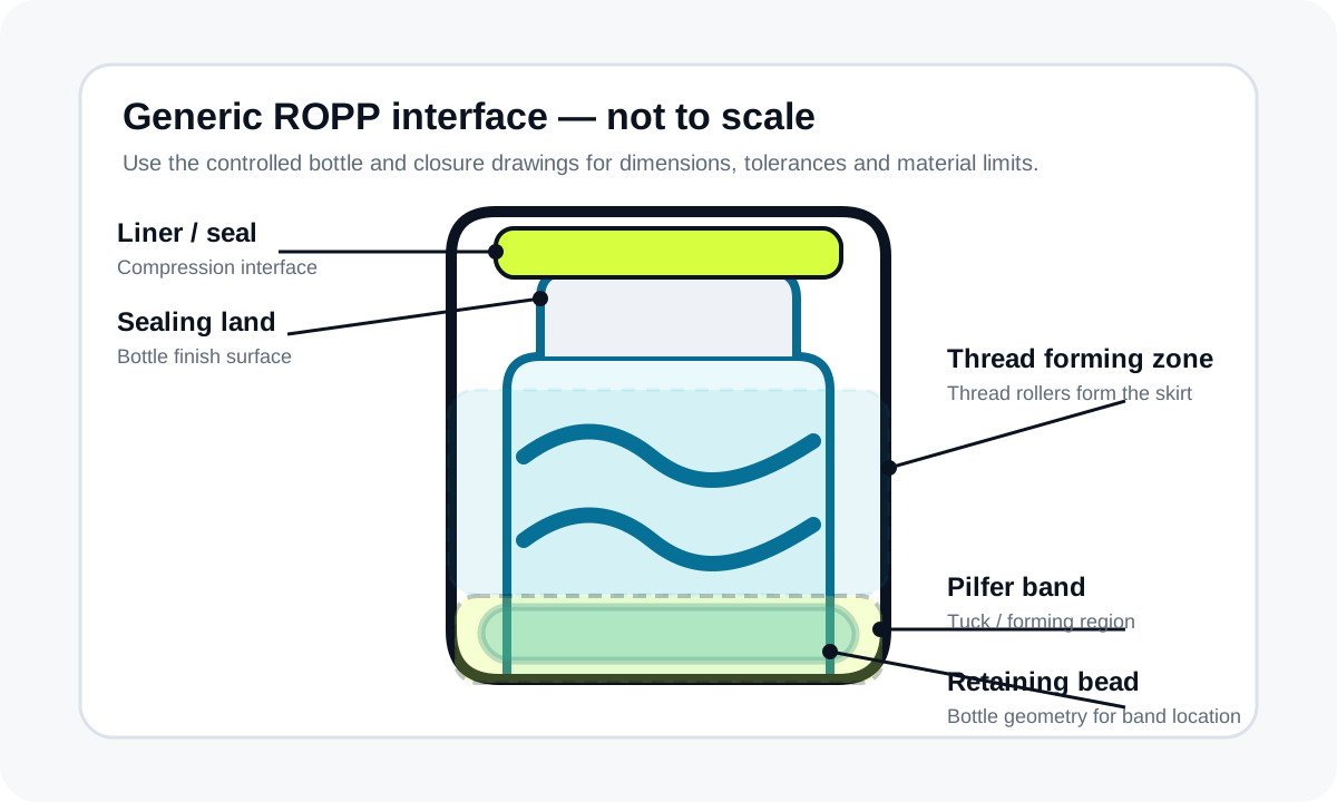
This non-dimensional diagram identifies the features to compare. It is not a manufacturing drawing and does not replace the bottle and closure suppliers' controlled drawings.
Use production samples to verify the drawing. A drawing can be correct while a mould, cap batch, liner or decorative finish varies enough to change the capping result.
| Tooling element | Function | Trial evidence |
|---|---|---|
| Pressure block or top pad | Seats the closure and establishes liner contact with the sealing land. | Cap height, liner compression, bottle damage and leak result. |
| Thread rollers | Form the aluminium skirt around the bottle thread profile. | Thread definition, opening feel, cap marking and reclose behaviour. |
| Pilfer-band rollers | Form or tuck the lower band beneath the retaining bead. | Band position, bridge condition, visible opening evidence and bottle damage. |
| Bottle support and guides | Keep the neck square and resist the forming force without distorting the pack. | Cap alignment, bottle stability, scuffing and repeatability at line speed. |
| Cap guide or feeder transfer | Presents the closure in the correct orientation and position before forming. | Misfeeds, cap skew, cap damage, starvation and restart behaviour. |
Sample-trial report
A useful report links every result to a packaging lot, machine configuration, head or station where relevant, instrument method and acceptance criterion. It should distinguish dry trials from filled-pack trials and record every deliberate setting change.
| Report section | Minimum record | Reason |
|---|---|---|
| Project and samples | Customer/project reference, date, bottle lot, cap lot, liner/insert, product condition and drawing revisions. | Prevents results from being applied to an untested packaging combination. |
| Machine configuration | Machine/model, capping head, roller set, bottle support, cap-feed method, format parts and recorded settings. | Allows the accepted set-up to be restored after changeover. |
| Run conditions | Requested speed, actual timed period, operator/feeder method, inspections, stops, rejects and environmental or conditioning notes. | Explains what the output figure includes and excludes. |
| Closure results | Cap height, thread and band appearance, opening torque, leak method, cap finish and any bottle or closure damage. | Connects machine settings to the pack-quality requirement. |
| Conclusion | Accepted sample reference, approved operating window, unresolved actions, repeat tests and sign-off owner. | Separates demonstrated evidence from assumptions still requiring approval. |
Acceptance tests
No universal torque or leak value is suitable for every ROPP pack. The target and method should come from the closure/bottle specification, product risk, customer requirements and the site's own quality plan.
Check cap height, square placement, sidewall marking, thread definition, band position, bridge condition and bottle damage against an approved sample or drawing.
Measure opening torque by a controlled method, observe bridge break and band behaviour, then assess thread engagement and reseal feel where the pack is intended to be reclosed.
Use the project-specific leak, inversion, pressure or storage method. Record product condition, temperature, dwell time and sample orientation so results can be compared.
On multi-head equipment, identify samples by head and test across the run. One incorrect head can create intermittent defects that disappear in an overall average.
Record cap starvation, jams, misorientation, bottle spacing, stop/start behaviour, rejects and recovery. A good closure result at low speed does not prove the full line.
Restore a previously approved format from the documented parts and settings, then repeat first-off quality checks. This confirms that acceptance is transferable to production.
Technical FAQ
No. Drawings define intended geometry, while production samples reveal material, mould, liner, coating and batch variation. Both are useful before tooling is approved.
Not necessarily. Opening torque is destructive, so a sampling plan may use separate identified sets for torque, leak, visual and storage checks. The report should state which sample set was used.
There is no universal quantity. The plan should cover packaging variation, every capping head where applicable, start-up, steady running, stop/start conditions and the confidence required by the customer's quality system.
It is a clearly identified capped bottle accepted against the agreed visual and functional checks, retained as a practical reference for future first-off inspection and troubleshooting.
Involve the supplier where drawing interpretation, liner behaviour, bridge design, torque target, material limits or unexplained cap damage needs confirmation from the closure owner.
Send the drawings, samples, test method and line requirements so Lancing can review the machine and tooling route.
Roller and tooling sequence
The capping head is a coordinated tooling system. Top load establishes liner contact, thread rollers form the skirt around the bottle profile, lower rollers form the pilfer band beneath the retaining bead, and bottle support keeps the neck square throughout the cycle.
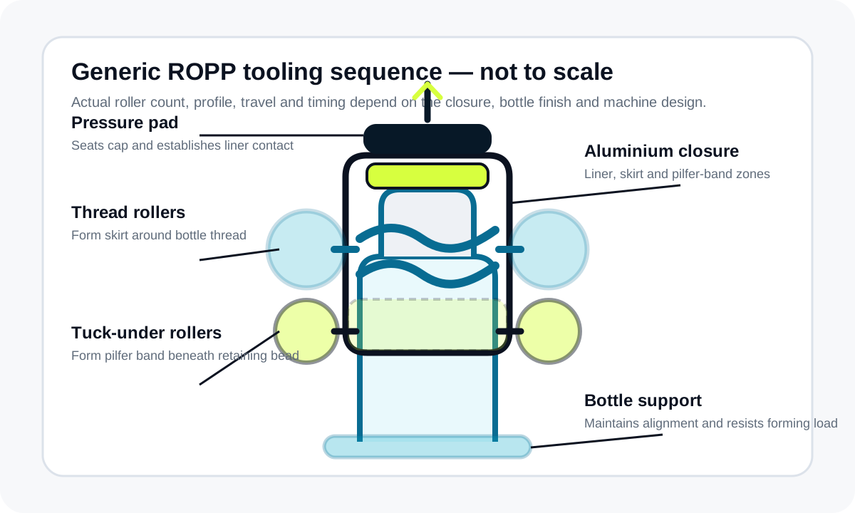
This explanatory diagram is not a manufacturing drawing. Roller count, profile, timing, approach and head construction vary by closure and machine; use controlled machine and closure information for production tooling.
A setting that improves one feature can worsen another. Evaluate liner contact, thread, band, torque, leak performance and appearance as one finished-pack decision.
| Controlled information | Details to obtain | Tooling or test decision supported |
|---|---|---|
| Closure drawing | Shell diameter and height, material, liner or insert, forming zones, band and bridge geometry, finish and tolerances. | Head size, pressure interface, thread/tuck roller position, cap guide and finish-protection requirement. |
| Bottle-finish drawing | Sealing land, thread profile, retaining bead, neck support features, critical heights, materials and tolerances. | Bottle support, roller travel, band location, cap height and compatibility review. |
| Production samples | Representative bottle and cap lots, decorative variants, liner/insert variants and any product-contact condition. | Actual tolerance behaviour, cap marking, stability, opening, leak and changeover evidence. |
| Machine tooling record | Head, pressure block, thread rollers, tuck rollers, supports, guides, starwheels and feeder parts by format. | Repeatable set-up, spare-parts identity and controlled changeover. |
| Acceptance method | Visual standard, opening method, leak/storage method, sampling, conditioning, run condition and sign-off owner. | Objective machine release and later production comparison. |
Evidence hierarchy
Neither source is sufficient alone. Drawings describe nominal geometry and tolerances; real packaging reveals lot variation, surface finish, liner behaviour, stiffness and handling effects. The trial record connects both to the approved machine configuration.
Check revision status and ownership. Confirm that the bottle and closure drawings belong to the samples supplied and that any liner, insert, pourer or finish variant is identified rather than treated as the same format.
Use production-representative quantities from more than one normal lot where practical. Retain uncapped controls, accepted capped bottles and failed samples in sequence with photographs and lot identity.
Record the exact tooling and settings that produced the accepted samples. A finished bottle without the corresponding head, rollers, supports, cap-feed parts and test method cannot act as a repeatable production standard.
A roll-on pilfer-proof head is intended to form a compatible aluminium closure around a matching bottle finish. If the cap is pre-threaded and only needs application torque, use the dedicated screw capping route. T-corks and other press-fit closures require a different application method rather than altered ROPP roller settings.
Lancing can review the bottle, closure, forming interfaces, output requirement and acceptance method before tooling is confirmed.
Technical document hierarchy
General guidance explains the process; supplier drawings and project acceptance records control the actual bottle, closure, tooling and finished-pack decision.
| Decision | Controlling evidence | Supporting guide |
|---|---|---|
| Is the bottle compatible? | Current bottle/finish drawing, closure drawing and representative samples. | Bottle neck finish guide |
| How is the cap sealed? | Closure supplier’s liner and application specification plus pack-owner quality requirement. | Liner and seal performance |
| Which tooling is required? | Approved bottle and closure samples, capping-head design and change-parts schedule. | ROPP capping-head guide |
| How is quality measured? | Named visual, dimensional, opening and leak/pressure methods with limits and sampling rule. | ROPP quality inspection |
| How is the machine accepted? | Quotation, approved scope, trial evidence, FAT/SAT plans and authorised deviations. | Factory acceptance testing |
Use the ROPP glossary to align buyer, closure-supplier, machine and quality language before drawings are issued.
Use the sample-trial guide to label packaging lots, machine conditions, first-off samples and raw results.
Use the ROPP machine videos to understand motion and layout, then confirm all performance claims through controlled trials.
CETIE publishes cap and finish data sheets, bottling guides and test-method recommendations relevant to several aluminium screw-closure systems. Select only the document applicable to the actual pack.
General guidance cannot approve an untested bottle, closure, liner, product or machine setting. Final selection requires the responsible packaging owner, closure supplier and machine team to agree the project evidence and acceptance method.
Send the current drawings, samples, test methods, line data and any rejected packs that need investigation.